Gerchberg-Saxton Correction
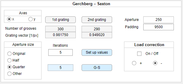
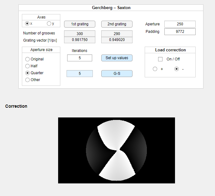
In this section, the process of correcting the optical setup with the built-in Gerchberg-Saxton iterative algorithm and the optical vortex image will be introduced. The panel responsible for adjusting algorithm parameters is presented below:
![]()
However, the user will have to use the optical vortex, blazed grating and aperture to find the proper algorithm parameters.
The procedure:
- Use the
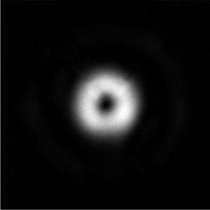
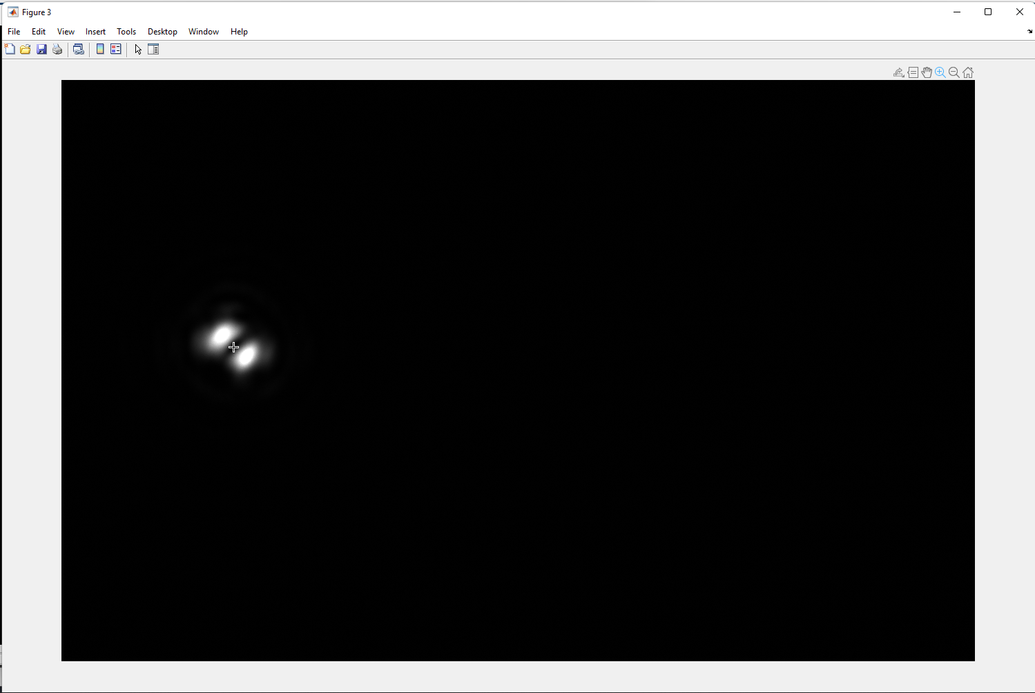
optical vortex,blazed grating, andapertureto align the optical setup so that the uncorrected vortex will be visible in 1st order of diffraction at the Fourier plane. The circular aperture is crucial for the algorithm to deliver correct results. In most cases, the distorted vortex of topological charge m=1 should resemble the one below (image of the vortex at Fourier plane, magnified by a 20x objective):
- Click the
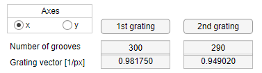
1st grating buttonin the G-S panel in order to upload selected diffraction grating parameters. - Choose the slightly different
blazed gratingparameters that will produce a similar image slightly shifted. Click the2nd grating buttonand upload the 2nd grating parameters. - Choose
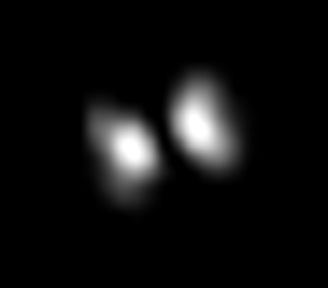
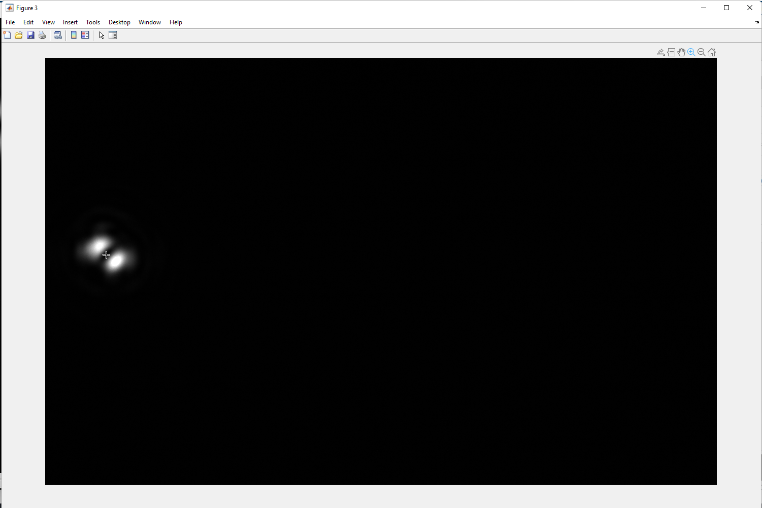
Axes(x or y), to determine which of theblazed gratingparameter was modified. For the best performance, we suggest not using the diagonal grating, therefore we limit possible options to either x or y grating shift. If diagonal grating is required, one can adjust the no. of grooves of the other component so that it’ll remain stable when switching from the 1st to 2nd grating. The exemplary case is presented below:
- Turn the
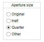
blazed gratingto off state and refresh the hologram using thestartbutton. The vortex image should disappear on the camera. - Choose the size of the aperture that should be used for an algorithm. It impacts the calculation time. The smaller the diameter of the aperture, the faster the algorithm. Usually, the quarter aperture, defined as the quarter of the diameter used to produce a vortex image, delivers sufficient results, however with the loss of hologram quality.
- Set the no. of iterations. Typically, 4-10 iterations are enough to produce sufficient results.

- Click the ‘Set up’ button to prepare the algorithm. The
optical vortexandaperturefunctions should be turned on, withblazed gratingleft as off. The LBSA will add the 1st blazed grating and capture the first image, then will repeat the process with the 2nd grating. - In the next steps, two images will be displayed, the user has to point and click the central position of the vortex. By default, each image is set into zoom mode, the first click will ‘zoom in’ to help the user determine the center of the beam. After the proper zoom is achieved, the
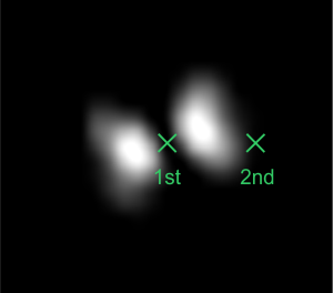
enterbutton on the keyboard stops the zoom mode and will let the user click on the vortex’ center. Below two images of the vortex are shown, respectively. The vortex center at each image is set pointed out using the cross pointer.
- Application will calculate the size of the matrix (edit field
Padding [px]), required for simulation. This size depends on the distance between two vortices produced by the proposed blazed gratings.
If the size of the matrix will exceed 11000, the whole procedure may be time-consuming. Therefore it is suggested to keep it below 11000. One may reduce this number by reducing further reducing the aperture and starting again from step no. 6.
- If all parameters are properly defined, the panel should resemble the example below:
- The
G-Sbutton will start the algorithm. In the first step, the function will capture the vortex image using the 1st blazed grating and let the user determine the size of the vortex. This will be done analogically to step 11, this time user will have to point to the center of the image (1st click after the zoom mode) and then to the side of the beam (2nd click on the left or right):
- In the final step, LBSA will determine the correction image using the built-in algorithm. This takes a few minutes, depending on the computer parameters. The final hologram will be displayed below the panel, simultaneously, the no. of iteration next to the
G-Sbutton will match the value chosen in step 7.
- Such an image should be subtracted from the currently displayed hologram. To do so, the user has to choose minus in the
Load correctionsection and enableonmode. Simultaneously, theblazed gratingtogether with theoptical vortexandapertureshould be turned on to produce the corrected vortex image: